Analysis of the Performance of A BAW Resonator According to its Design Parameters
We present in this paper a brief review on the use of acoustic waves in designing MEMS based resonator. Acoustic devices are classified into two basic types – Surface acoustic wave (SAW) and Bulk acoustic wave (BAW) devices. A BAW resonator is modeled and simulated using COMSOL Multiphysics 5. In this model variation in thickness and piezoelectric material is the prime focus for studying the basic variation in resonance frequency and the quality factor Q of the BAW device. In comparison with bibliography we obtained a better result of resonance frequency and quality factor, when we reduced the thickness of the piezoelectric layer less than 16, 7um used at, fr= 222 MHZ, Q= 1326. According to our study the better result is found with Aluminium Nitride (AIN) with thickness13um, fr= 302 MHZ and Q >2200
Keywords:Bulk Acoustic Waves; BAW Resonators; Piezoelectric Material; Resonance Frequency; Qality Factor
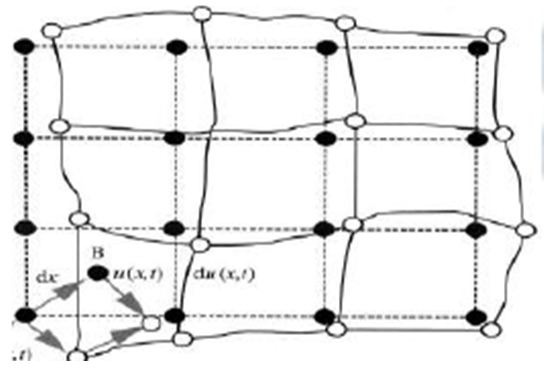
Acoustics is the study of time-varying deformations or vibrations within a given material medium. In case of solid, it is the result of deformation of the material. Deformation occurs when atoms within the material move from their equilibrium position which results in internal restoring forces that return the material back to equilibrium. Figure 1 depicts the equilibrium and deformed states of particles in an arbitrary solid body- the equilibrium state is shown by solid dots and the deformed state is shown by circles [1].
Acoustic wave can be induced by a variety of methods such as mechanical impact, pulsed thermal energy, and inverse piezoelectric effect.
Acoustic devices are employed in manufacturing transducer which can be broadly classified into two groups: surface acoustic wave (SAW) and bulk acoustic wave (BAW) devices [3].
In this paper we will study the influence of variation in thickness and piezoelectric material of BAW resonator, to attain high quality factors with a minimised structure compared to reference [4]. We reduced the thickness of the piezoelectric layer from 16, 7um to 13um and we used three piezoelectric materials Aluminum Nitride, Lithium Niobate and Zinc Oxyde. We used these three materials in our work because they present a high quality factor at high frequencies compared to other materials used in bibliography. For instance, Lead Zirconate Titanate (PZT-8) [4]. The Quality factor is the most important characteristics of a resonator because it describes the frequency selectivity of the device [5].
That’s why in this work we analyze the performance of BAW resonator with three different piezoelectric materials ZnO, AIN and LiNbO3, according to various thicknesses.To find suitable solutions for designing BAW resonators operating at high frequencies with a high Q factor.
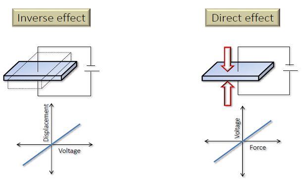
Piezoelectric crystals play crucial role in the communication and electronics industry in areas like filters, precision timers and frequency control in oscillator circuits [6-9]. This effect is demonstrated in the Figure 2. Piezoelectric material tends to get deformed due to the applied potential across its two surfaces (direct effect) and when a force is applied on the piezoelectric material, a potential appears between its two surfaces (inverse effect). This is due to coupling of linear elasticity and electrostatic charge.
Hooke’s law for elasticity may be written as:
The Strain-Charge form: [10].
The Stress-Charge form: [10].
T = stress; S = strain; E = electric field;
D = electric displacement
CE = elasticity matrix ; e = coupling matrix ;
εS = permittivity matrix
sE=compliance matrix d=coupling matrix ; εT=relative permittivity
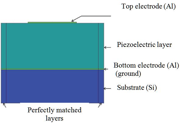
Bulk acoustic wave promises frequency in GHz range when integrated with RF circuits along with small size resonator and filters [11-14]. The resonator is of thin film type in which the substrate is etched away on the back side [11,14,15]. The natural frequency of the material fr= νa/2d - with νa the acoustic velocity of the piezoelectric material and the thickness are used as design parameters to obtain the desired operating frequency. The BAW resonator is modelled by sandwiching a piezoelectric layer between two electrodes as shown in Figure 3. A thick silicon layer is etched as the bottom layer and a potential drop is applied between the two electrodes and the admittance in the piezoelectric layer is calculated. The bottom electrode is made the ground layer. Table 1 shows the different used dimensions.
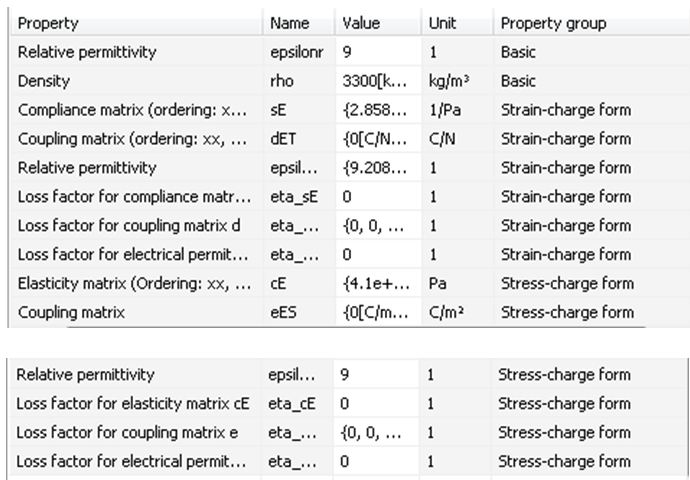
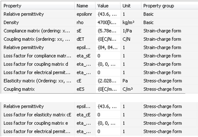
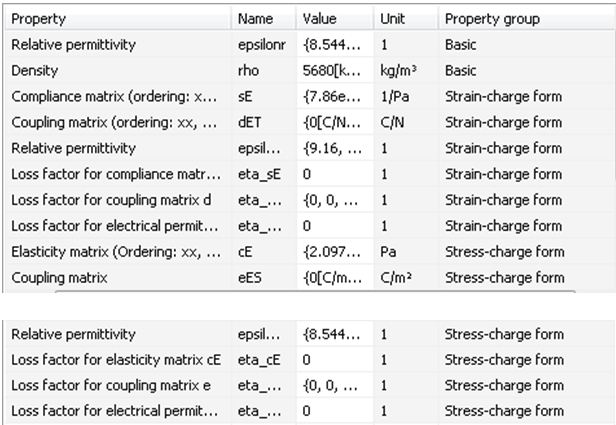
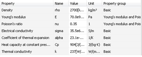
We used in our study three piezoelectric materials, Aluminium Nitride AIN, Zinc Oxyde ZnO and Lithium Niobate LiNbO3. Tables below show the properties of different used materials obtained from Comsol Library.
The design of the BAW resonator in COMSOL environment starts with selecting “Physics”: Structural Mechanics-Piezoelectric Devices, then we select “Study”: Frequency Domain. After that we build our geometry, and we define materials for each layer using the “Material Library” of COMSOL.
Then in “Solid Mechanics” in the model Builder we define in our geometry linear elastic material (electrodes) and piezoelectric material (piezoelectric layer), and we set the PML (perfectly matched layer) on the two sides of the resonator to simulate the effect of propagation and absorption of elastic waves in the adjoining regions. After that in “Electrostatics” we define the bottom electrode as a ground and we set the top electrode to 1V to generate an acoustic wave in the bulk of piezoelectric material. After all these settings we mesh the structure with a “Normal” type meshing. And we run the simulation.
This model consists of two thin film metal layers (with Aluminium), piezoelectric layer and a silicon substrate as displayed graphically in Figure 3. The bottom layer is the silicon substrate, on top a thin metal layer serving as the ground electrode. A thin piezoelectric layer is sandwiched between two metal layers. It may be noted that the top metal serves as the positive electrode while the bottom is the ground electrode, a potential is applied between them. Table 1 shows the used dimensions.
All simulations are performed in COMSOL Multiphysics 5 environment [16,17]. It is a finite element analysis; solver and simulation software packaged for various physics and engineering applications, especially coupled phenomena, or Multiphysics. All the geometrical measurements were carried out using the MEMS module present in the software tool. Figures below shows the obtained admittance (in S) as a function of frequency (Hz) and the quality factor Q of the modelled resonator according to the dimensions of the piezoelectric layer and according to the different used piezoelectric materials.
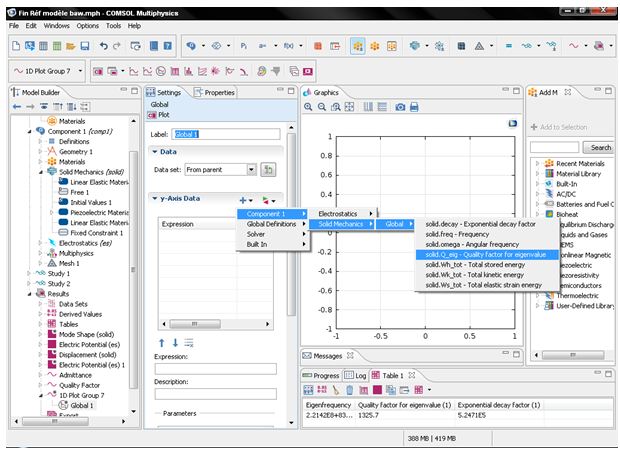
Figure Below shows how we simulate the Quality factor Q in Comsol environment.
Figure 5 and Figure 6 shows the influence of the decrease of the thickness of piezoelectric material on the resonance frequency according to the different used materials. From the graphs it’s clear that the value of the resonance frequency is inversely proportional to the thickness of piezoelectric material. Therefore, as the thickness decreases, the resonance frequency increases. As seen from the graphs too, it’s found that the resonance frequency is higher for resonator using Aluminium Nitride AIN compared to resonators using ZnO or LiNbO3 at the same thickness. This is due to higher acoustic velocity of AIN which is 10400 m/s compared to ZnO and LiNbO3.
Figure 7 and Figure 8 shows the influence of the decrease of the thickness of piezoelectric material on the Quality factor Q of the resonator according to the different used materials. From the obtained results, the finding shows that the quality factor is inversely proportional to the thickness of piezoelectric material, that’s mean when we decrease the thickness, the Quality factor increase. It’s also observed that the Quality factor is higher for resonator using AIN compared to resonators using ZnO or LiNbO3.
Table 6 summarizes all the obtained results.
In comparison with bibliography we obtained a better result of resonance frequency, and quality factor; when we reduced the thickness of the piezoelectric layer less than 16, 7um used at [4]. The results obtained in reference are fr= 221MHZ and Q= 1326 for ZnO. With our simulations we obtained better result with LiNbO3 and AIN with the thickness 13μm; fr= 302MHZ and Q >2200 [4].
This work presented a design and analysis of BAW resonators using FEM Analysis. The influence of the decrease of the thickness of piezoelectric layer and comparing various piezoelectric materials were analysed and explored to find suitable solutions for designing BAW resonators operating at high frequencies with a high Q factor which helps us to implement extremely selective IF and RF filters.

.JPG)
.JPG)
.JPG)
.JPG)
.JPG)
.JPG)
.JPG)
.JPG)
.JPG)
.JPG)
.JPG)
.JPG)
