Diesel Spray Behaviour and Air Entrainment
Formulation of diesel spray tip penetration is one of the basic research works of diesel spray. Since physical relationships among various injection parameters of diesel spray are included in the equation of spray tip penetration, it becomes a fundamental “tool-equation” for diesel spray analysis and improvement of diesel spray combustion. There have been many proposals of spray tip equation but most of them were derived from experimental data obtained by classical jerk injection system. They have received some critical comments of mismatch with experimental results of up-to-date injection system. Since diesel spray injection system has been changed from jerk pump system to high pressure common rail system, empirical equation of spray tip penetration have to be modified or optimized for new injection system. In this report, spray tip penetration equation obtained by Hiroyasu and Arai was modified to match for common rail injection system with high pressure rise. It shows that initial injection rate has strong influence on spray tip penetration. Similarity law of tip penetration was derived by determinative model of breakup time and breakup length. Combustion of diesel spray is considered to be controlled by spray angle and air entrainment, and both of spray angle and air entrainment have direct relationship with spray tip penetration. Then the additional derivation of spray angle and air entrainment was carried out based on the new equation of spray tip penetration and momentum conservation. Formulated analysis shows that spray angle is controlled by contraction ratio of fuel jet at nozzle exit and air entrainment has strong relationship with tip penetration.
Keywords: Diesel spray; Spray tip penetration; Spray angle; Air entrainment; Empirical equation; Similarity law
List of abbreviations: Cv: Velocity coefficient [-]; Cc: Contraction coefficient of jet [-]; Dn: Nozzle diameter [m]; Kbl: Coefficient of breakup length (= α) [m0.5]; Kbt: Coefficient of breakup time [m0.5]; Kp: Coefficient of penetration [m0.25]; Kv: Velocity coefficient of nozzle, (= Cv) [-]; Lb: Breakup length of liquid jet [m]; Lt: Breakup time of liquid jet [sec];Ma: Mass of entrained air [kg]; Mf: Mass of fuel [kg]; Pa: Ambient pressure [Pa]; Pinj: Injection pressure [Pa]; ΔP: Effective injection pressure [Pa]; S: Spray tip penetration [m]; Ŝ: Spray tip penetration before breakup [m]; S*: Non-dimensional spray tip penetration [-]; S(tc): Momentum center penetration [m]; t: Elapsed time from injection start [s]; t*: Non-dimensional time from injection start [-]; U: Spray tip velocity after breakup [m/s]; U: Spray tip velocity before breakup [m/s]; Uinj: Injection velocity [m/s]; α: Coefficient of breakup length [m0.5]; β: Coefficient of tip penetration [m/s0.5];Pa: Ambient gas density [kg/m3]; ρl: Liquid fuel density [kg/m3]; φ: Spray half angle [deg.]; φ*: Spray half angle [deg.]; θ: Spray angle [deg.]
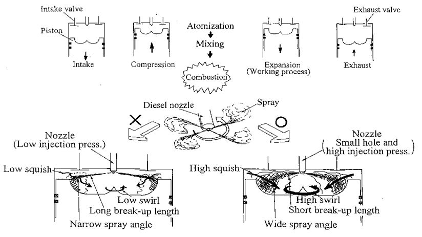
Solid fuel spray so called diesel spray was characteristic naming to an intermittent high speed fuel spray formed in high pressure diesel combustion chamber. Its macroscale behavior was characterized by spray tip penetration and spray angle. Also its microscale behavior such as turbulent mixing with surroundings was characterized by macroscale air entrainment behavior that has strong relationship with penetration and angle of the spray. Figure 1 is an illustration of diesel spray behavior and its combustion in a DI diesel engine [1]. From an injector set on the cylinder head, diesel fuel was injected into a combustion space. It penetrated in the space accompanying with air entrainment, and formed a suitable mixture for combustion. There were many parameters affecting mixture formation and combustion of diesel spray. Liquid fuel atomization process so called breakup process of liquid jet, spray penetration, spray angle, wall impingement and resultant air entrainment were physical parameter of spray. Even though these parameters were sometimes affected by swirl and squish air motion induced by piston movement, they were main physical parameters of diesel spray combustion.
There were many empirical equations of spray tip penetration and spray angle [2]. These equations were used to evaluate injector performance, to make matching between diesel spray and combustion cavity, to check the accuracy of diesel spray simulation, and for other purpose including injector and engine designing (for example, down-size engine designing). Since physical relationships among various injection parameters of diesel spray are included in an equation of spray tip penetration, it was also used as a fundamental “tool-equation” for diesel spray analysis and for improvement of diesel spray combustion.
However these empirical equations had also received some critical comments of mismatch with experimental results. For example, spray tip penetration equation proposed by Hiroyasu and Arai showed under-estimated result for high pressure injection and their spray angle showed over-estimated result for up-to-date diesel spray [3]. These mismatches are usually considered as accuracy limit and difference of injection system, but we need more fundamental discussion on these mismatch reasons.
Since diesel spray injection system has been changed from jerk pump system to high pressure common rail system, empirical equation of spray tip penetration have to be modified or optimized for new injection system. Here spray tip penetration obtained by Hiroyasu and Arai was modified to match for common rail injection system with high pressure rise. This modification was verified using reference penetration data obtained other researches. Spray angle and air entrainment to diesel spray have more direct relationship with diesel combustion. Then the additional discussion on them was performed based on the new equation of spray tip penetration. One of the authors already proposed a new spray tip equation as a brief report, but we need more detail discussion on modification and on theoretical relationship among spray penetration, spray angle and air entrainment [4].
There are many reference reports concerning diesel spray behavior including its evaporation and combustion. D. L. Siebers et al. analyzed the relationship between spray penetration behavior and combustion [5-7]. They considered that the liquid length (breakup length) was a key parameter of diesel spray combustion. R. Payri, et al. also derived the theoretical model of spray tip penetration and discussed the relationship between injection rate and breakup length [8-10]. S. Martinez, et al. reported empirical equation of penetration [11]. Transient spray characteristics of spray penetration and spray angle were discussed with G. Zhang, et al., Y. Li, et al. and BW Knox, et al. [12-16]. Optical characteristics of common-rail injection diesel spray were reported by G. Lequien, et al., Y. Jung, et al., F. R. Westle, et al., R. Lockett, et al. and N. Maes, et al. [17-21]. As for theoretical treatment of diesel spray, K. Inagaki, et al. reported air entrainment estimation of down-sized diesel spray [22-23]. Other important advance and recent information relevant to diesel spray behavior were introduced by author’s monograph [24]. However, general relationship between diesel spray penetration and air entrainment into it seems to be not enough discussed, especially for high pressure injection diesel spray. Then fundamental diesel spray penetration behavior was discussed here using the basic concept of liquid breakup and momentum conservation.
Veniamin G Levich obtained breakup length concept of a liquid jet under the following assumptions [25],
(i) Liquid jet of density ρl is moving in a gaseous medium with density, ρa << ρl.
(ii) Relative velocity between liquid jet and gas medium is large.
(iii) Amplitude of liquid jet surface disturbance is accelerated by pressure disturbance of gaseous medium.
(iv) As the amplitude of surface disturbance increases, the jet tends to be unstable, and finally, it may be breakup into droplets.
(v) Breakup length, Lbis calculated from breakup time, tb.

Where Ữ means sectional mean injection velocity of liquid jet and Dn is nozzle diameter of injector. Furthermore Hiroyasu, et al. assumed that [3]

(vi) Injection pressure and injection rate are constant during injection period.
(vii) Spray tip velocity, Ữ within intact length (before breakup) is constant, and coincides with initial jet velocity Uinj,

Here, Cv is velocity coefficient of injector nozzle. In this case, transient behavior of initial pressure rise did not considered and extremely low value of velocity coefficient was assumed. Effect of initial pressure rise on injection velocity is explained latter in session under 'Verification of Modified Equation' heading.
(Viii) Spray tip penetration S is proportional to √t, based on momentum conservation and continuous jet theory of Wakuri [26].

Transient time (breakup time, tb) from start of injection to jet breakup is obtained from Vinj) and Lb.

At t = tb), spray penetration should coincide with Lb, and β can be obtained as follows.
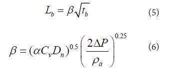
Finally, Hiroyasu and Arai obtained following empirical equation of diesel spray penetration, breakup length, and breakup time.
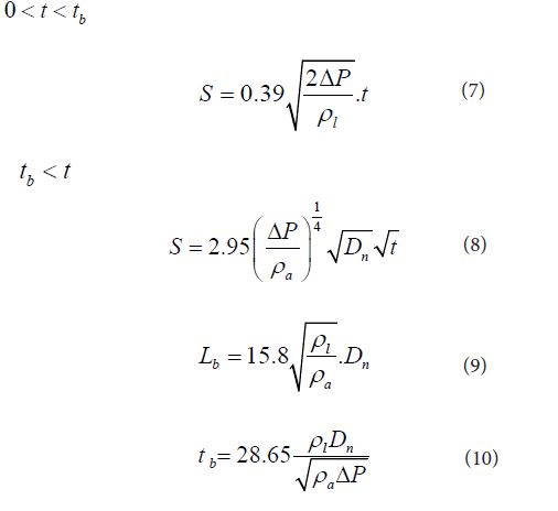
Here ΔP means the effective pressure for injection. Difference of opening pressure of injector driven by jerk pump system and ambient pressure is adopted by the original empirical equation. Relationship among the numerical coefficients in Eqs. (8), (9) and (10) were determined by Eqs. (4), (5) and (6) and two of these three parameters could be set independently
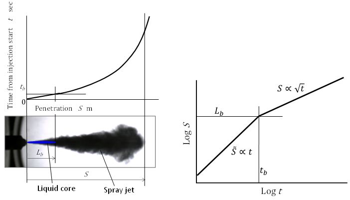
According the equation of penetration mentioned above, we could introduce the penetration model of diesel spray. From equation (7), liquid jet penetrated with constant velocity until breakup. Its velocity had to coincide with injection velocity. At this standpoint, coefficient of 0.39 in Eq. (7) was too small when it compared with the conventional velocity coefficient of nozzle. This discrepancy came from the overestimation of injection velocity, because opening pressure of needle valve in the injector was used as the injection pressure and actual effective injection pressure was usually lower than the opening pressure. This overestimation of injection velocity is discussed later in section 3.2. After the period of breakup, spray suddenly changed to spray and its movement was controlled by momentum conservation principle shown by Eq. (3) of jet. Breakup form liquid jet to spray started actually just after injection and gradually proceeded until it penetrated to the location of Lb. However in the center portion of liquid jet, breakup process was delayed and un-breakup liquid remained. It corresponded spray tip of initial stage of injection. In other words, spray penetration model introduced here was a determinative breakup model of high speed liquid jet.
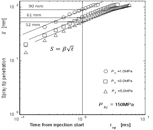
Spray penetration model could be illustrated as shown in Figure 2. Estimated liquid jet portion in the spray photography was indicated as the liquid core and its length corresponded to the breakup length shown by Eq. (5). Even though using up-to-date optical method, optical determination of liquid core length was difficult. However using the assumption shown by Eq. (2), it could be estimated by logarithmic t-S diagram. Since spray tip movement was proportional to t or √t, logarithmic t-S diagram was convenient to show the clear difference of penetration before and after breakup. Logarithmic t-S diagram could show the determinative penetration model of early stage penetration. Using the model and photographic spray data, we could determine coefficients in Eqs. (9) and (10) those were suitable for the observed spray.
Diesel spray was injected into confined combustion cavity shown in Figure 1 and its auto-ignition occurred with short ignition delay after injection start. Since ignition delay was usually shorter than 1 msec and first flame kernel of auto-ignition appeared around spray, intensity of initial combustion stage so called premixed combustion was greatly affected by early stage spray behavior and entrained air before ignition. Then spray tip penetration and air entrainment during early stage of injection was important of first priority [27-30]. Further, following diffusion combustion coupled with wall impingement was controlled by the air entrainment. Even though the spray movement and air entrainment after wall impingement were affected by wall geometry, their behavior was controlled by spray penetration, because original driving force of mixture formation was supplied form kinetic energy of spray [31-34]. It meant that later spray penetration after ignition had another importance on diesel combustion.
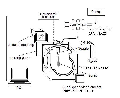
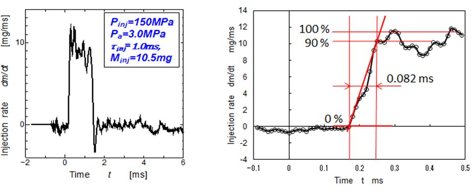
Validation check of previous equation was performed on experimental data obtained by high pressure common rail injection system [35,36]. Figure 3 was the setup of spray injection experiment and Table 1 was the injection condition for experiment. Injection rate pattern was measured by Bosch type long tube method and shown in Figure 4. Initial pressure rise of this injection system is relatively high, and injection with almost rectangular injection pattern was obtained. Since, in general, spray tip penetrated more than 20mm during initial 0.1 msec, the initial rise of injection rate until 0.1ms from the start of injection was one of the important parameter of spray tip penetration. In this injection system, response time up to 90% of regulated injection rate was around 0.08msec. It might be enough short for validation study of spray penetration. In Figure 4, injection started at 0.27ms position of horizontal axis (tentative time axis). Then, actual origin of elapsed time for analysis was set at 0.27ms position on this tentative time axis.
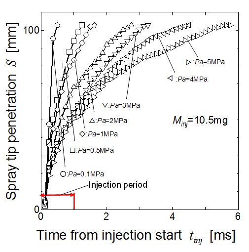
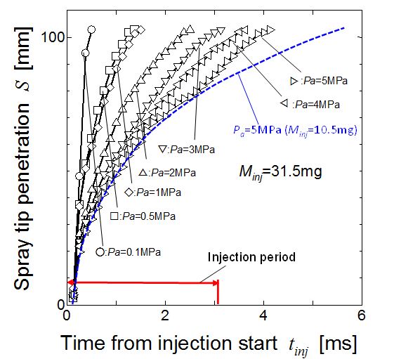
Examples of time-to-penetration diagram of diesel spray injected by this system are shown in Figure 5. Injection pressure Pinj was 150 MPa and injection duration was 1.0 msec. When the injection period changed from 1.0 msec to 3.2 msec, injection mass changed from 10.5 mg to 31.5 mg, because the rectangular injection pattern was maintained by the special common rail controller. However spray penetration characteristics was hardly changed as shown by Figure 6. Dotted line in Figure 6 showed the reference spray penetration of 1.0 msec condition. Spray tip penetrations in both figures were almost in a time range from start to 2 msec. After 2 msec, stagnation effect of short period injection appeared. As for the purpose of penetration equation modification, spray penetration around breakup point and penetration area from injector to combustion cavity wall was important as explained in section 2.3. Then only the data before 2 msec shown in Figure 5 were used in the following analysis.
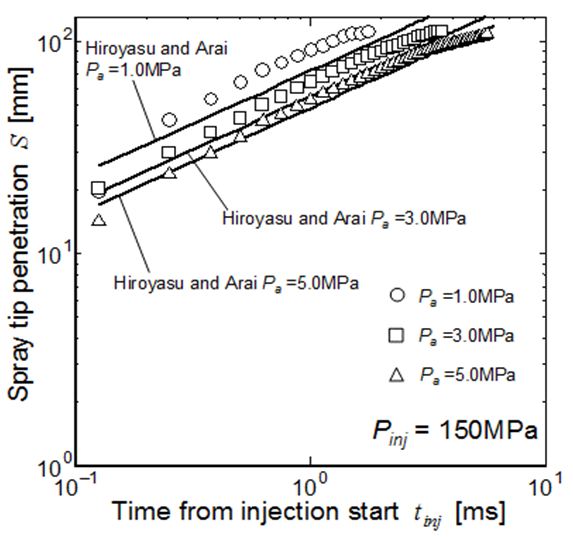
Logarithmic expression of penetration data shown in Figure 5 and estimated penetration by Eq. (8) were compared by the plots and lines in Figure 7. Here pressure difference between common rail pressure and ambient pressure was adopted as the effective pressure in Eq. (8). Unfortunately, owing not enough time resolution of the data, penetration behavior before tb could not be checked by this comparison. Since the old data used for derivation of Hiroyasu and Arai equation were obtained from high speed photographs of jerk pump system and initial injection velocity was not so high and enough time resolution could be attained. However it became difficult to obtain the early stage penetration data of high pressure common injection spray.
Spray penetration increased proportionally with √t, but its absolute value was around 30% higher than the penetration line estimated by the original penetration equation. One of the considerable reasons of this mismatch came from the different evaluation of effective pressure and the other was unclear velocity coefficient of injector. Then we have to modify the penetration equation.
Before the start of modification, spray tip penetration was rearranged using four non dimensional parameters Kv, Kbl, Kbt and Kp. Here, Kv = Cv is velocity coefficient of nozzle and 0.39 was used in the original equation shown by Eq. (7). Kbl and Kbt are breakup parameters of length and time, and Kp means the tip penetration parameter. Eqs, (13) and (14) give inter-relationship among these four parameters and only two of four parameters are independent parameters.
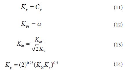
Then final equations of spray tip penetration and spray tip velocity are as follows.
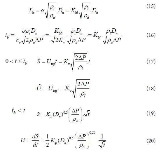
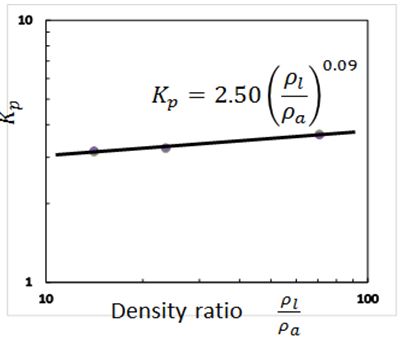
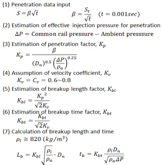
Table 2 shows the procedure of parameter estimation. Parameter estimation started at β using Eq. (3). shows practical β estimation diagram using the same penetration data as Figure 5 and Figure 7. Since the spray tip penetration around t =1 msec was important for actual diesel spray penetration (refer ‘Penetration model and real spray’ section), spray penetration S at t =1.0 msec was adopted for this estimation. After then, Kp was obtained using Eqs. (5) and (19). Figure 9and Eq. (21) show the obtained relationship between Kp and density ratio.

The effect of density ratio on Kp looks like very small. To simplify the final penetration equation, here, Kp is assumed to be constant.

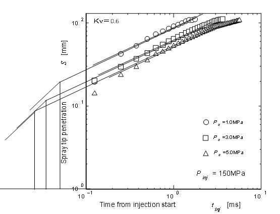
If we consider a free liquid jet discharge from orifice with no friction, Kv = Cv =1.0 should be adopted but friction loss should not be neglected for actual diesel nozzle. Then value of 0.6 or 0.8 is adopted as velocity coefficient (Kv = Cv) and other parameters are obtained according the procedure in Table 2. Spray penetration parameters obtained here are listed in Table 3. Here values ofKv, Kbl, Kbt and Kpfor original equation were experimentally obtained by Hiroyasu and Arai and used in Figure 7 for comparison. The values for modified equation were corresponding to the common rail injection spray. It shows that values of Kbl, Kbt and Kp are changed with Kv but experimental determination of Kv is usually difficult. Then two possible cases of Kv are shown in the Table.
Figure 10 shows the final result of spray tip penetration. In this case, velocity coefficient Kv = 0.6 was used. From the equation of breakup length Eq. (15), breakup length around 10 mm was calculated, and breakup time was less than 0.08 msec. It suggested that breakup length was remained even though high pressure injection, but breakup time was almost same order of injection rate rise shown in . It meant that initial injection rate had strong influence on spray penetration and high speed camera of 100k fps was needed to catch the spray behavior before breakup. Owing some assumptions such as Kp by Eq. (22) and other data fitting, there were small differences between experimental data and predicted ones.
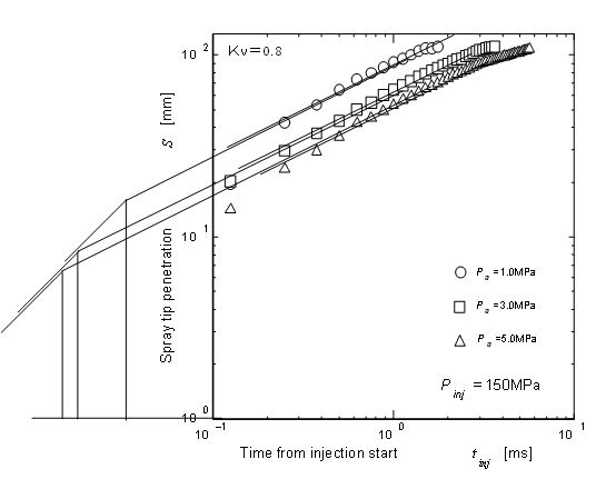
When the velocity coefficient Kv = 0.8 was adopted, different combination of Kbl and Kbt was obtained as listed in Table 3. As shown by Figure 11, earlier breakup time and shorter breakup length were estimated by Kv = 0.8 assumption but overall penetration result using Kv = 0.8 was almost same as Kv = 0.6. It means that combination of parameters was more important than the individual numerical value of parameters.
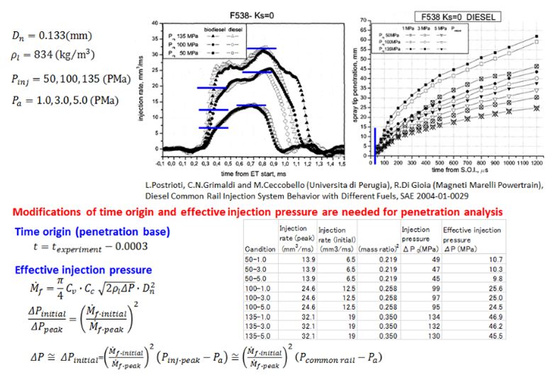
Verification of modified equation was done using the penetration data reported by L. Postrioti, et al. [38]. These penetration data were obtained by conventional common rail injection system. Generally, spray tip penetration was affected by the initial pressure rise or initial rise of injection rate. They affected spray tip penetration through effective injection pressure of initial stage. Then the initial effective pressure was estimated using the actual injection rate reported in the reference paper. Figure 12 explains the data pre-arrangement to obtain the initial effective pressure. In this case, initial effective pressure was estimated by the regulated injection pressure and actual injection rate at early stage of injection. It was revealed that the initial effective pressure of this reference data was less than 50% of regulated injection pressure as shown in the Figure. Time origin of injection start was another problem of verification. Actual time origin was extrapolated using injection pattern and t-S diagram of early stage.
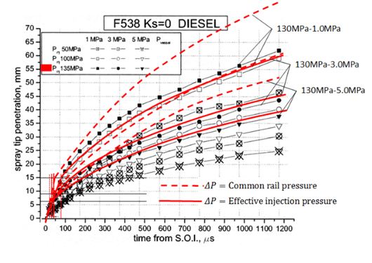
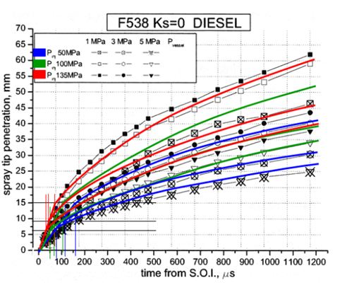
First verification was done for 130MPa injection case shown in Figure 13. Here common rail pressure (regulated injection pressure) was used as the effective pressure in modified equation. There are big differences of spray tip penetration estimated and experimentally obtained one. It suggested that this mismatch was mainly caused by over-estimation of injection pressure. In other words, initial effective pressure was a key concept of penetration matching. Figure 14 shows the predicted spray tip penetration using initial effective pressure obtained by the procedure shown in Figure 12. It shows that predictions using modified equations with modified initial effective pressure match well with experimental measurement. It also shows that the injector-to-injector dependent parameters are effective injection pressure and velocity coefficient. Spray tip penetration can be completely predicted when these two items are accurately predicted.
Similarity law of diesel spray is important to find the general concept of diesel spray and its combustion [38 ]. When non-dimensional scales of time and penetration length are introduced using Eqs. (23) and (24), spray tip penetration can be simply expressed by Eqs. (25) and (26) [1]. Here t* and S* are non-dimensional break up time and scale. It meant that characteristic time and length of breakup phenomena gave similarity scales for spray tip penetrations of various kinds of sprays not only diesel sprays but also sprays in many engineering fields.
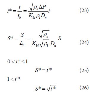
Liquid jet atomization process has various mode of breakup with different mechanism. Since the base of this similarity law is coming from a determinative breakup model introduced by Eq. (1) and momentum conservation of resultant spray, it can be applicable for various sprays with atomization processes different from diesel spray. Application of scale similarity law of diesel spray is considered as follows
(1) Non-dimensional comparison of diesel sprays of various conditions.
(2) Engineering suggestion of diesel spray for down-sizing engine.
(3) Engineering suggestion of diesel spray for high boosted engine.
(4) Deeper physical understanding of diesel spray.
(5) Easy application of engineering knowledge of diesel spray to other spray engineering.
As shown Eq. (23), time scale was proportional with 1/Dn , It means that diesel spray injected from smaller scale injector decays faster than that injected from larger one. On the centrally, ignition delay was controlled by chemical process of fuel mixture and does not changed by engine size. It results engineering difficulty of downsizing matching between injector and engine bore size, because engine speed does not changed.
Spray angle was combined with spray tip penetration through momentum conservation of spray jet. From the momentum conservation and Wakuri’s theory, spray angle was expressed as follows.


Here,ϕis a half angle of spray jet. Using this equation, spray angle reported by Wakuri, et al. was rearranged and following equation for spray angle is obtained.

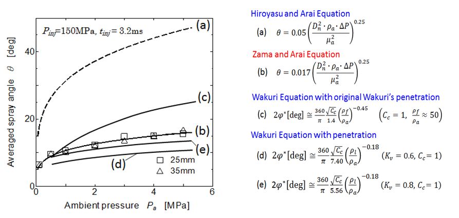
Here Cc is contraction coefficient of nozzle exit. When diesel spray was injected into elevated pressure surround-ings such as 1.5 MPa, cavitation effect on contraction coefficient was week and Cc=1 could be assumed. Further Hiroyasu and Arai rearranged Eq. (27) and obtained empirical equation of spray angle.
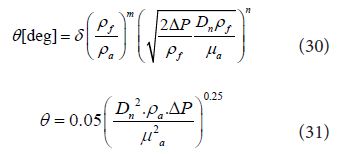
Main difference between Eq. (27) and Eq. (31) is the effect of ambient gas density effect. Wakuri’s equation considered only the effect of density ratio expressed by ρf /ρa, but Hiroyasu and Arai considered independent effect of ambient gas density. Recently, Eq. (31) was modified by Zama, et al. for high pressure common rail injection system and they proposed following equation [40].

Using spray parameter obtained here, Eq. (28) can be arranged as follows.

When Kp is constant and is independently determined by Eq. (22), spray angle is independent from ambient den-sity. However empirical equation such as Eq. (32) clearly shows that ambient density is independent parameter apart from density ratio of ρf/ρa , Then using Eq. (21), new equation of spray angle is derived as follows.

Contraction coefficient Cc of nozzle exit does not appeared in penetration equations mentioned above. It is newly introduced in Eq. (28). It means that additional physical parameter in needed to explain the behavior of diesel spray angle. In other words, spray angle is more strongly affected by nozzle configuration than spray penetration.
Figure 15 shows comparison of experimentally obtained spray angle and angles obtained by various equations mentioned here. Experimental data of spray angle were obtained from measured spray width at 25mm and 35 mm apart from injector of common rail injection system [19]. Estimation lines of (a) and (c) were obtained from Eqs. (31) and (29). Since these previous equations were obtained from sprays injected by jerk pump system and injection pressure evaluation was not accurate, these equations over-estimated spray angle. Equation (b) was the modified one for common rail injection system used here and there is no special reason that it had some estimation error, because Eq. (32) was obtained by these experimental data. Equations (d) and (e) (corresponding to Eqs. (34) and (35)) were derived by momentum conservation theory and spray tip penetration obtained here. The under-estimation of these two equations came from the assumption of cone shape configuration of the spray (see the spray configuration suggested by dotted red line in 17). Experimental spray angle was affected by the definition of spray side boundary. 10% photo-density threshold was adopted to obtain spray angle in the figure. However spray angle might become narrow when 30%photo-density threshold was used. Considering this uncertainness of spray angle obtained from photograph, assumption of Kv = 0.8 and Cv = 1.0 (Eq. (35) is a reasonable combination for spray angle estimation. In other words, spray angle obtained from momentum conservation showed little bit narrower angle than actual spray angle. Main physical difference among these equations is the exponent of ambient pressure/density term. It suggests that air entrainment mechanism based on turbulence is differently estimated in those equations.
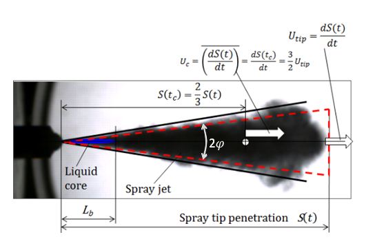
General concept of momentum conservation is shown in Figure 16. Momentum of spray before air entrainment consists with the momentum of liquid fuel with initial injection velocity. After air entrainment being processed, spray mass increases by entrained air and velocity of spray decreases. Using momentum average velocity of spray, momentum conservation can be expressed as follows.

Since spray tip and spray tail have different velocities, following momentum average velocity of spray is needed to obtain the total air entrainment.
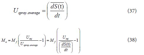
Here, 

Then air entrainment during injection period can be obtained by integration of following equation.


Here, 
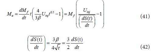
Location of momentum center can be find by spray penetration velocity (at time tc) that is correspond momen-tum average velocity.

Using Eq. (39) and Eq. (43), location of momentum center S(tc) is expressed as follows

Figure 17 shows the momentum center and momentum average velocity of spray. Here spray tip penetration could be easily measured by photographic image but liquid core length measurement needed other method such as electrical resistance method or advanced optical methodologies [20,21,39]. However spray cone correspond-ing the average spray boundary could be determined from shadowgraph image of the spray. Above analysis shows that air entrainment has strong relationship with spray tip penetration. When a spray volume was meas-ured by image processing, total entrained air could be obtained by following equation.

As for a developed spray, air volume of spray was far larger than liquid fuel volume (Va >> Vf ), and entrained air could simply be obtained by spray volume. When tip penetration and spray angle of diesel spray was known such as Eqs. (19) and (33), and homothetic (similitude) development with constant spray shape were maintained, spray volume and entrained air could be obtained using Eqs. (46) and (47).


Here constant spray angle and conical spray shape shown in Figure 17 are assumed. Considering the relationship among β and other penetration parameters, Eq. (47) coincides with Eq. (40) except the term “t”, because liquid fuel volume was neglected in Eq. (47).
It is well known that later stage of diesel spray combustion is a diffusion combustion and mass burning rate in diffusion combustion process is controlled by air entrainment rate. Air entrainment rate can be derived from Eq. (47) and is expressed as follows.

It shows the air entrainment rate increases gradually with the time. Injected fuel mass is proportionally in-creased with ΔP0.5 but entrained air increases with ΔP0.75. It means the combustion improvement effect of high pressure injection [40,41].
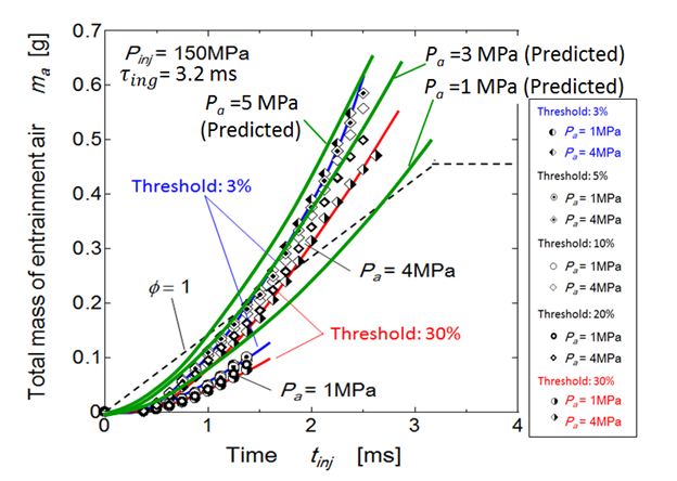
Predicted air entrainment by Eq. (40) and experimentally obtained air entrainment using Eq. (45) are compared in Figure 18. Injection duration of this experimental data was 3.2 msec and other injection conditions were almost same as the previous data Figure 6. In the Figure, two experimental data (Pa =1MPa and 4MPa) based on different spray volume boundaries and three predicted air entrainment lines (Pa =1MPa, 3MPa and 5MPa) are plotted. At early stage of injection, since the breakup time was neglected in the prediction, the predicted en-trainment was somewhat larger than the entrainment by volume measurement. However, increasing tendency of predicted air entrainment was well matched with experimental data. It suggests that air entrainment and spray tip penetration has direct relationship expressed by Eq. (40). Dotted line (Φ =1) indicated total air mass that was needed to make stoichiometric mixture. It suggested that enough air was entrained during injection period when the ambient pressure was high, but was not entrained enough when ambient pressure was low such as 1MPa(Figure 18).
Fundamental analysis of spray tip penetration was reviewed and modification of penetration equation was per-formed for high pressure common rail injection diesel spray. Spray tip penetration, spray angle and air entrain-ment were rearranged here to make clear relationship among diesel spray parameters. Main conclusions are as follows
(1) Penetration equation of Hiroyasu and Arai was well modified for diesel spray injected by common rail injection system.
(2) Verification of modified equation of tip penetration revealed that initial rise of injection rate or injection pressure was domination factor of spray penetration matching.
(3) Using breakup length and breakup time, similarity law of spray tip penetration was derived for general study of diesel spray..
(4) Modified spray angle based on momentum conservation was well fitted to the experimental results..
(5) Contraction ratio of liquid jet at nozzle exit did not affect tip penetration but it directly affected spray angle..
(6) Relationships among tip penetration, spray angle and air entrainment were formulated.
(7) Above relationships revealed that air entrainment had strong relationship with spray tip penetration..

