Effect of Aligned Implants on the Stress Promoted by Loads in Fixed Partial Prosthesis: A Photoelastic Study
This in vitro study verified the effect of aligned implants on the stress in partial fixed prosthesis when the teeth were submitted to axial or oblique loads. A photoelastic model (n=1) was made for each implant type (EH - External hexagon, IH - Internal hexagon, and MT- Morse taper) in which were placed three aligned implants, and a Ni-Cr framework with three units. The prostheses were subjected to axial (AL) or oblique (OL) loads of 100 N applied on the occlusal of the teeth. A polariscope analyzed the photoelastic behavior of the models with Fringes software in Matlab platform. Qualitative analysis: EH/AL - Lower stress at second premolar and greater stress concentration at implant apexes of the first and second molars; IH/AL - Less stress concentration at second premolar and first molar, and larger stress at implant apex of the second molar; MT/AL - Different stress concentrations in the implant regions with more intensity at implant apex of the second premolar; EH/OL - Greater stress concentration at apex regions of the first and second molars; IH/OL - Greater stress concentration at apex regions of the first and second molars; and MT/OL – Greater and similar stress concentration at apex regions of the second premolar, and first and second molars. Quantitative analyses: EH/AL (T=18.24 and Nf=1.82); IH/AL (T=18.14 and Nf=1.81); MT/AL (T=18.27 and Nf=1.81); EH/OL (T=20.13 and Nf=2.01); IH/OL (T=19.84 and Nf=1.89); and MT/OL (T=20.22 and Nf=2.02). In conclusion, linearly aligned implants in partial fixed prosthesis promoted similar stress concentrations when the teeth were submitted to axial or oblique loads.
Keywords: Dental Implant; Partial Fixed Prosthesis; Photoelasticity; Induced Stress
There is a concept that the control by the dentist of occlusal forces in the oral rehabilitation with dental implants would be more significant than in natural teeth. Based on theoretic consideration and clinical experiences with the Brånemark system, the force excess occurs in areas of the implant/abutment and implant/bone interfaces. Therefore, in normal oral conditions the load supported by the implant is transferred to alveolar bone without severe damage to prosthetic restoration [1]. Conversely, the bending moment resulting from non-axial overloading of dental implants may cause stress concentration exceeding the physiological capacity of the cortical bone leading to various failure types [2].
Cusp inclination and location of the natural tooth alter the distribution force pattern which influence the micro movement induced by the periodontal ligament. In osseointegrated dental implants do not exist movement associated to load distribution because the implant/bone interface is different from that which occurs in natural teeth. Changes in cusp inclination and tooth location are conditions that decrease or increase the overload on dental implants [3].
It is alleged that the location of the occlusal loading influences the stress distribution levels in the implant-supported partial fixed prosthesis and supporting alveolar bone. The occlusal loading location may increase or decrease the stress on the metal framework and bone, and the optimal combination for vertical loading was with loading at 2 or 3 locations which decreased the stresses in the alveolar bone [4]. Partial fixed prosthesis is more susceptible to bending loads due to difference in mobility between teeth and implants; however the frequency of implant overload in posterior partial prosthesis is considered lower, and with appropriate planning almost always preventable [5].
External hexagon, internal hexagon and Morse taper are connections of dental implant platforms. Advantages, disadvantages, and different clinical indications have been the purpose of researchers using different methodologies to verify the stress occurred during the loading of implants with different connection configurations [6-12].
Photoelasticity is used for construction of models and interpretation of tensions. This method allows to observe the distribution of stress throughout the structure, enabling a general insight of the behavior of the stresses. Two types of fringes (stress) are revealed using polariscope: colored patterns (clear) called isochromatic fringes that represent the intensity of the stresses; and the isoclinic dark lines overlapping the colored fringes related to direction of the tensions.
The preview of the internal stress is the major advantage of the photoelastic method based in the passage of light through of the model, and in the generation of colorful patterns proportional to exercised stress. The main informations required in dentistry for photoelastic studies are location and intensity of stress concentration that can be photographed and/or measured. On the other hand, in analytical methods, as three dimensional finite element analysis (3D-FEA) and strain gauge analysis, is necessary to built graphics and distribution scheme of forces from numeric data [6,13].
The alignment of implants showed controversial findings in different studies. Changes in the angle of load application showed greater stress in the supporting alveolar bone, and middle implant placed in an offset configuration may reduce the stress; however, the reduction did not compensate the increase occurred with off-axis loading offset placement showed no advantage for the stress decreasing over the aligned placement angled and straight systems promoved similar stress distribution around the implants and displaced placement reduces the strain around the implants; however, axial or non axial loadings have not influence until 2 mm [14-17].
Considering these different findings, the purpose of this in vitro study was to verify by photoelastic analysis the effect of aligned implants on the stress promoted by axial or oblique loads exerted on the teeth of partial fixed prosthesis. The hypothesis tested was that linear alignment of implants would promote different effects on the stress induced when the teeth were submitted to axial or oblique loads.
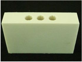
Three rectangular models (46x30x10 mm) with three holes distant 3 mm among them were made using NURBS (non-uniform rational b-spline) Rhinoceros 5 Program (Rhinoceros NURBS modeling for windows; Robert McNeel, Seattle, WA, USA). This method allows modeling complex structures and exportation in the STL format (stereolithography file). This format creates a mesh of the model allowing manufacture by the 3D printing process. The STL model was sliced into layers, generating a g-code sent to a 3D printer (Sethi3D AiP; Sethi Eletronics, Sao Paulo, SP, Brazil). The printer uses fused deposition modeling (FDM) technology in which the material has been liquefied and deposited in 0.3 mm layers, and after cooled and solidified to form the models (Figure 1).
The respective analogs of the implants were fixed in the models with cyanoacrylate glue (Super Bonder; Loctite, Sao Paulo, SP, Brazil), the square transferees connected to the analogs, and the bond between them made with dental floss and acrylic resin (Duralay; Reliance Dental, Chicago, IL. USA). The impression of the models was made with industrial silicone (Sapeca Arts and Crafts, Bauru, SP, Brazil) using a rigid PVC ring as customized tray.
After silicone polymerization at room temperature, three cylindrical implants of each type (EH - External hexagon, IH - Internal hexagon or MT - Morse taper; Conexao Implant Systems, Sao Paulo, SP, Brazil) with similar sizes were linearly placed in each mold, and connected to the square transferees for impression. Next, the photoelastic resin (PL-2; Vishay Measurements, Raleigh, NC, USA) was manipulated according to manufacturer’s instructions and placed in the silicone mold. The molds were left in a vacuum chamber with a pressure of 40 lbf/pol2 for 24 h to remove possible residual air bubbles.
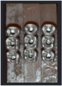
The crown models were made using 3 Series Scan (Dental Wings-DWOS; Montreal, Canada), waxed according to teeth anatomy, and casted. The fixed partial prosthesis with three units (second premolar, and first and second molars) were conventionally casted with Ni-Cr alloy (Fit Cast-SB Plus; Talladium, Curitiba, PR, Brazil), and screwed in the respective photoelastic models (Figure 2).
After, loads of 100 N were exerted in the directions axial (AL) or oblique (OL - 45 degrees from buccal to lingual) over a metal splint placed in the occlusal surface of the teeth in the area corresponding to the first molar tooth [12]. The stress was observed with a circular polariscope (LPM-FEMEC-UFU; Uberlandia, MG, Brazil), and the photographs were taken with a digital camera (Nikon D80; Nikon, Tokyo, Japan).
The qualitative analysis was based on the spectrum observed in the filter analyzer showing typical colors for the following fringe orders: Fringe order Nf = 0 (Black); Fringe order Nf = 1 (Violet/blue transition); Fringe order Nf = 2 (Red/green transition); Fringe order fringe Nf = 3 (Red/green transition); and Fringe order Nf = 4 (Red/green transition).
The qualitative analysis was visual and the quantitative analysis was made by a graphic software (Fringes; MATLAB Plataform, LPM-FEMEC-UFU). The following experimental groups were accomplished: EH/AL – External hexagon implants linearly placed, master screw connection, UCLA, and axial load; IH/AL- Internal hexagon implants linearly placed, master conect Ar connection, UCLA, and axial load; MT/AL- Morse taper implants linearly placed, master AR morse connection, UCLA, and axial load; EH/OL- External hexagon implants linearly placed, master screw connection, UCLA, and oblique load; IH/OL- Internal hexagon implants linearly placed, Master Conect Ar connection, UCLA, and oblique load; and MT/OL- Morse taper implants linearly placed, Master AR Morse connection, UCLA, and oblique load.
The analysis of the fringe patterns was accomplished by a color scale, considering that the isocromatic fringes are defined by the Fringes program according to stress levels at a given point in the model. The values of the color scale were visualy adjusted by the specific color pattern by means of a calibration table of the Fringes program. The specific color pattern was converged for a final value of the fringe orders (Nf) in a data grid.
For the standardization of reading of the fringe orders, in the photoelastic model were considered 12 points distributed around each implant. The points were mapped according to obtained images in the photoelastic models. All models were analyzed using template with measures of width and length corresponding to dimensions of photoelastic model, and the selected points from the grid inserted in the Fringes program.
Statistical analysis for T (MPa) was accomplished by two-way ANOVA followed by Tukey’s test at significant level of α=0.05. The factors analysed were type of implant and load application.
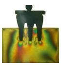
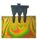
EH/AL - Axial load applied on the teeth promoted lower stress concentration on the implant apex of the second premolar and greater at apexes of the first and second molars (Figure 3).
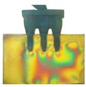
IH/AL - Axial load applied on the teeth showed less stress concentration on the implant apexes of the second premolar and first molar, and larger stress at implant apex of the second molar (Figure 4).
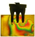
MT/AL - Axial load applied on the teeth promoted different stress concentrations in the implant regions with more intensity at implant apex of the second molar (Figure 5).
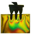
EH/OL - Oblique load applied on the teeth promoted greater stress intensity at apex regions of the second premolar and first molar when compared to second molar (Figure 6).
IH/OL - Oblique load applied on the teeth showed greater stress intensity at apex regions of the second premolar and first molar when compared to second molar (Figure 7).
MT/OL - Oblique load applied on the first molar promoted greater stress at apex regions of the second premolar, and first and second molars (Figure 8).
Table 1 shows the shear stress means (T - MPa) and fringe order (Nf) for the axial or oblique loads exerted on the teeth with implants linearly positioned. There was no statistically significant difference among T means in the associations related to the same load type. Values for Nf were similar among the groups related to the same load type.
The qualitative analysis showed similar patterns of stress distribution in aligned implants for all implant/load associations when the teeth were submitted to axial or oblique load of 100 N (Figures 3,4,5,6,7 and 8). There was not statistically significant difference for stress shear (T) when the same load type was considered, and the fringe order (Nf) values were also similar for the same load condition (Table 1). Considering these results, the hypothesis tested that linear alignment of implants would promote different stresses on partial fixed prosthesis when the teeth were submitted to axial or oblique load was rejected.
It is a general concept that the implant can favorably tolerate the axial loads whatever the type of prosthetic connection. In normal practice conditions, the stress is distributed on the implant threads without significant damage to prosthetic restoration, and later transferred to surrounding alveolar bone [1]. Conversely, the bending moment resulting from non-axial overloading of dental implants may cause stress concentration exceeding the physiological capacity of cortical bone, causing different types of failures in the prosthetic components. Therefore, tensile and compressive stress values on cortical bone in the cervical region of the implants showed lower stress values on cortical bone in the cervical region for wider implant configuration placed in aligned position [2].
Several factors are responsible for the transference of forces from the prosthesis to implants and alveolar bone. Increase or decrease of the stress concentration levels depends of different combinations for vertical loading/number of load location on the occlusal surface of teeth in implant-supported partial fixed dentures and surrounding alveolar bone. The optimal combination to decrease the stress in alveolar bone was vertical force and loading at 2 or 3 locations [4].
According to a strain gauge study, three Morse taper implants placed in straight line or offset configurations showed that the configuration factor was statistically significant; however, the load factor (axial and nonaxial), and the interaction between the two factors were not significant. There was evidence that offset placement is capable of reducing the strain around the implant. In addition, axial and nonaxial forces did not show influence when applied until 2 mm from the center of the implant [17]. Moreover, loading of 100 N exerted on the 3-unit implant-supported prosthesis showed lower stress using a external hexagon conection than Morse taper configuration. The oblique loading promoted a higher stress concentration that axial loading [18].
The findings of the current study do not agree with the aforementioned results because the qualitative analysis showed similar stress distributions in aligned implants for all configurations when loads were exerted simultaneously on the three teeth (Figure 3,4,5,6,7 and 8). Similarly, no statistically significant difference for T values was shown among the groups whatever the load type, and values of Nf were also similar in all combination implant type/load direction (Table 1). Therefore, there are evident reasons to believe that the load simultaneously distributed on the three teeth of the prosthesis was responsible by the similarity of shear stress pattern (T) and fringe order (Nf) at implant apex and alveolar bone.
Based on the concept of stress distribution in complex structures, it can be assumed that the mechanical behavior of prosthetic structures submitted to simultaneous loading on all teeth would be different than those exerted by single load on the molar tooth whatever the direction of the force. Probably by this reason, there were different levels of stresses at the implant apex and alveolar bone when the partial fixed prosthesis supported by implants with different connections was submitted to single axial or oblique loadings on the molar tooth [12].
The concept of stress distribution in complex structures seems appropiate in relation to external hexagon, internal hexagon and Morse taper connection systems. This implants when submitted to axial loading showed similar stress values. However, oblique load increases the stress on prosthetic components and alveolar bone while internal connection presents more favorable stress distribution than external connection system and even that the offset placements show the benefit of decreasing the bone stress, the offset placement provided no advantage for the stress decreasing in the in-line placement because the stresses at cortical and trabecular bones around the implant was similar with aligned or offset placements [11,15].
Different methodologies evaluating the relation among different configurations in implant-supported prostheses showed that the internal hexagon and Morse taper connections did not reduce the microstrain around implants although the type of implant connection system did not have direct influence on the stress distribution for axial loading, the cantilever length showed direct influence on stress distribution and under vertical load applied at center or away from the center of the implant, the internal hexagon showed the least stress concentration when compared to external hexagon configuration [9,19,20].
However, a finite element analysis for single-unit implant restoration suggests that the off-axis loading provides a significant contribution to increase stress at implant/cortical bone interface, and the distance off-axis at which the force is exerted is also a significant factor [21]. In agreement, 3D-finite element study showed that oblique force produces more stress than vertical force. Non-rigid connector resulted in decrease in stress at prosthesis and increase at alveolar crest under progressive loading (180, 180, 120, 120, 80 N on the first and second molars, premolar and canine, respectively) and simultaneous loading (100, 100, 100, 100, 100 N on the same teeth, respectively) [22].
According to bone physiology theory, bones under mechanical loads adapt their resistance to load applied by means of modeling/remodeling, condition that may be applied to the alveolar bone surrounding of dental implant. The response to mechanical stress below a certain threshold strengthens the bone by increasing of the density or apposition of boné, and the fatigue micro-damage resulting in bone resorption may be due to mechanical force beyond this threshold. Although the results are conflicting, animal experimental studies have shown that occlusal load might result in marginal bone loss around dental implants or complete loss of osseointegration [23]. In addition, the rehabilitation with dental implant treatment is often improved when implants are placed in dense alveolar bone, the number of supporting implants are increased, the implant placement configuration reduces the negative effect of bending moment, and when the prosthesis is placed in clinical use [24].
An in vivo study showed that the amount of peri-implant crestal bone changes significantly among all time-phase pairs for all implant-abutment connection, being greater in the healing phase than in loading phases. However, the peri-implant crestal bone change did not differ significantly among the types of implant-abutment connections during the healing phase and loading phases. This retrospective clinical study reveals that the design of the implant-abutment connection appears to have no significant impact on short-term peri-implant crestal bone change [25]. An interesting approach made in a previous work showed that the tension around the implants increases with the decrease in the number and distribution of implants in implant-supported partial fixed dental prostheses for the anterior maxilla [26].
In clinical studies, an combination between loading conditions and marginal bone loss around dental implants or complete loss of osseointegration has been stated, but a causative factor was not shown and the number of implants with different configurations has been responsible by the different stress concentration levels, resulting in different changes at alveolar bone during the healing phase are different facts that could be considered as a possible limitation of this in vitro study which would be the reason for further studies on the subject [23,25].
The following conclusions may be considered: (1) Implants linearly aligned promoted similar effects on the stress in partial fixed prosthesis when the teeth were submitted to axial or oblique loads. (2) Qualitative analysis showed similar stress distributions, and quantitative analysis showed similar values for T and Nf in all associations.