Liquid Layer Precipitate PM Permeated from Pool Diffusion Flame
Carbonaceous deposit on piston surface of internal combustion engine was caused by fuel film adhered on the surface. It became many trouble sources such as knocking and HC emission. However the formation mechanism of carbonaceous deposit was unclear phenomena because the deposition was slowly grew up during long term operation of the engine. Particulate matter (PM) formed in combustion field was permeated into fuel film and stayed as precipitate PM in the film. It became carbonaceous deposit when fuel film was evaporated. In this study, carbonaceous deposit caused by precipitate PM permeated from flame zone into fuel film layer was fundamentally investigated using small pool diffusion flame of liquid fuel. Mass of precipitate PM in the pool was collected as a deposit on the pool bottom. From the comparison of pool fuel evaporation and pool flame combustion, it was confirmed that the deposit was mainly caused by precipitate PM permeated from flame zone and liquid fuel pyrolysis had slight effect on it. Test fuels were n-Heptane (C7H16), n-Octane (C8H18),iso-Octane (C8H18), Benzene (C6H6) and Toluene (C7H8). Deposit formation rates from aromatic hydrocarbons such as Benzene and Toluene were higher than those of n-Octane and iso-Octane. To clarify the thermophoresis effect on permeation, pool flame was heated up by a coil heater. Deposit formation ratios (relative mass ratio to fuel consumption) increased with decreasing of fuel consumption rate at both of the normal and heated flames. These ratios had clear relationship with temperature gradient near fuel surface. It was estimated that precipitate PM and deposit formation was controlled by the thermophoresis effect near fuel surface.
Keywords:Deposit; Permeate PM; Precipitate PM; Pool Flame; Thermophoresis
It has been known that nanometer size PM (nano-PM) is formed in combustion field such as diesel and gasoline engines [1-5]. The weight ratio of nano-PM in engine emission was very low; however, considerable number of nano-PM was formed in engine. Since nano-PM is harmful to human health, new technologies should be established to remove the exhaust emission of Nano-PM.
Further, some of PM was deposited on piston and cylinder wall, and it resulted another troubles such as low thermal efficiency, knocking and hydrocarbon (HC) emission. Surface deposit in an engine cylinder prevented heat transfer and resulted hot surface spot to induce knocking. Deposit layer absorbed unburned fuel vapor and became a source layer of HC and nano PM emissions. These deposit problems existed since early development age of internal combustion engine but it had not considered with nano-PM problem. Recently nano-PM emission problem and thermal efficiency of internal combustion engine were received much attentions and also deposit PM problem relevant with nano-PM emission was closed up for internal combustion engine with high efficiency and bio-fuel utilization. Caceres, et al. reported the effect of combustion chamber deposit (CCD) on life cycle emission of small utility engines. They pointed out the 50 % HC+NOx emission increase by CCD formation operation of 200 hours [6]. Cerit, et al. analyzed piston temperature affected by the deposit. They showed that 50 μm thickness deposit of the piston surface resulted 50 oC increase of surface temperature [7]. Wang, et al. investigated deposit effect on GDI injector flow [8]. They reported that coked and clean injectors showed different manner of atomization of liquid fuel. Yamada, et al. studied combustion chamber heat loss problem relevant with the deposit using a thin film thermocouple [9]. Zerda, et al. investigated pore size distribution and microstructure of combustion engine deposit and found the graphitic structure of soot deposit [10].
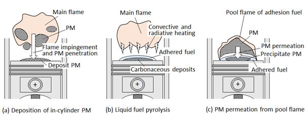
As for the deposit layer formation, three possible mechanisms can be considered as illustrated in Figure 1. First is in-cylinder PM deposition. PM is formed in fuel rich flame zone and it penetrates and deposits on the wall. This mechanism is shown in Figure 1(a). It has strong relationship with PM formation in combustion process and wall impingement of flame. This type of PM deposition is almost same as the quenching PM deposition when a flame is touched to the wall [11]. The second is carbonaceous deposit formed directly by pyrolysis of liquid fuel adhered to the wall. This second type of formation mechanism is known as carbon flower sticking to the injector nozzle and wall deposit in bio-fuel operation Figure 1(b). As for a direct injection gasoline engine, fuel film combustion coupling with PM formation sometimes occurred on the piston wall, and the resulting PM might be permeated to the liquid fuel layer on the wall.Figure 1(c) shows this type mechanism of deposit layer formation. Since the pool flame combustion and pool flame PM formation in engine cylinder is not yet clarified, PM permeated from pool flame to liquid fuel film is a vague process that should be clarified.
Wall deposition mechanism of PM formed in a flame was performed as a fundamental study of diffusion flame and its quenching. Hayasida, et al. investigated soot formation process using LIF [12]. Kobayashi, et al. measured nano-PM size in diffusion flame [13,14]. Paul, et al. investigated carbon nanoparticles in a partially premixed flame [15]. As for the flame impingement, Zhang, et al. investigated nanoparticle transport and deposition in boundary layer of stagnation-point of premixed flame [16]. They reported the contribution of Brownian diffusion on the deposition flux of PM. Deposit PM on a quenching metal mesh was investigated by Kobayashi,et al. [17]. They reported the mass and density of deposition PM. Bouvet, et al. simulated stagnation flow and clarified the particle motion near the wall [18]. Brownian motion of nanoparticles and thermophoresis effect on it was reported by Guichard, et al.. and other adhesion mechanisms were reported by Liu, et al. [19,20]. Above research works have given much information concerning the deposition if in-cylinder PM shown in Figure 1(a). Research of PM in liquid fuel pool and PM deposition on the fuel bottom at lower temperature condition was especially important for cold start deposit in internal combustion engine. However there are no practical research works on it because it is strongly complicated phenomena of PM behavior in the cylinder.
Liquid fuel pyrolysis is the second mechanism of deposit formation (Figure 1(b)). It becomes serious problem when bio-fuel is used as a diesel fuel. It depended on the fuel properties, spray formation process and wall impingent and adhesion fuel film on the wall. Then deposit formation and its effect on engine performance were the first category of the research works. Kalam, et al. investigated deposit characteristic when crude palm oil was used [21]. They showed that the oxidation characteristics of carbonaceous deposit from adhered fuel film were greatly affected by the ash in the fuel. Kidoguchi, et al.. studied deposit problem of DI diesel engine fueled by straight rapeseed oil [22]. They studied the formation process of adhered fuel film by evaluating fuel impingement behavior and the lubricant oil dilution on the piston wall surface. Basic studies (second category) of fuel pyrolysis on a hot surface were performed by Arifin, et al. and Furuhata, et al. [23-29]. They reported that slow pyrolysis and oxidation of fuel film on a hot surface produced carbonaceous deposit and proposed empirical formula that estimated the deposit mass. Fuel film was generally vaporized on the hot wall but fuel pyrolysis and carbonization were simultaneously taken place. It became the carbonaceous deposit on the wall. Carbonaceous deposit formation and its oxidation were greatly affected by the fuel properties such as boiling point and chemical composition of fuel. Surface temperature of the deposit was higher than the bottom wall temperature when the deposit oxidation was initiated.
As for the third type mechanism, Hu, et al. summarized pool fire behavior and explained heat feedback mechanism from pool diffusion flame to fuel pool [30]. Merola, et al. reported the deposit formation by a diffusion flame that took place on the adhesion fuel near intake port of port-injection gasoline engine [31]. Ketterer, et al. proposed the low oxygen pool flame as a combustion mechanism of fuel film on the piston of a DISI engine [32]. Su, et al. investigate split fuel injection effect on gasoline engine PM and suggested much of PM was produced by wall impingement of the fuel [33]. However they did not clarify the PM formation mechanisms related with (a) and (c) mechanisms shown in Figure 1.
Recently, nano-particle fluid such as Sisko nanoliquid, Oldroyd-B nanoliquid and others were investigated by T. Hayat, et al.[34-38]. They studied the nanoparticle mixture motion in the fluid where Brownian motion and thermophoresis were key phenomena of particle motion, heat transfer and mass transfer in a nanoparticle mixture fluid. However, PM precipitate motion through the interface between gas and liquid fluid was more complex phenomena. It was affected not only by Brownian motion and thermophoresis in gas and liquid phases but also by molecular and particle dynamics on the surface. According this view point, PM precipitate mechanism contained in the phenomena shown by Figure 1(c) had deep scientific meaning beyond the engine PM deposition.
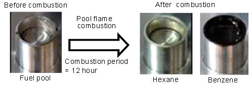
In order to investigate formation process of PM and its characteristics, a small pool combustion equipment in which stable diffusion flame was formed by liquid fuel, was developed [13,14]. Stable pool flame could be formed using the pool combustion equipment during an hour and more long combustion period; however fuel pool was sometimes contaminated by a long time combustion operation (over 2 hours). Figure 2 shows the example of fuel pool contamination after diffusion combustion for Hexane and Benzene fuels. Pool flame of Benzene resulted obvious contamination comparing to Hexane flame. Color of contamination substance was brown or black, and depends on fuel. The fuel pool contamination might be caused by permeation of solid particles from the flame into the fuel pool.
Since the similar phenomena of fuel contamination might occur during liquid film combustion in internal combustion engine, it was thought that fuel pool contamination research gives us available information to obtain knowledge about deposit formation relating fuel film combustion and PM permeation mechanism shown in Figure 1(c). In this study, then, PM permeation to fuel pool and formation of precipitate PM in the fuel pool during pool combustion with liquid fuel were investigated. Moreover, the influence of flame hearing on deposit formation in the fuel pool was investigated to understand the driving force of PM permeation into the fuel pool.
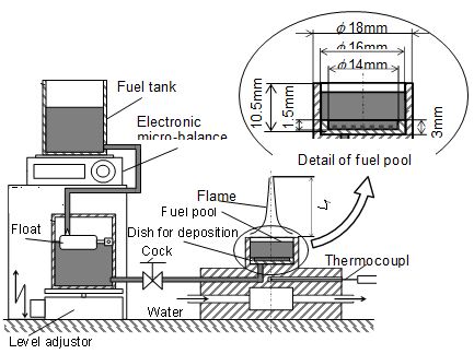
Pool combustion equipment was used to form a laminar diffusion flame of liquid fuel. Figure 3 shows the scheme of the equipment. It consisted of a fuel tank, a fuel supplying system, a fuel pool and an electric microbalance. The fuel was supplied from the fuel tank through a float chamber. The float chamber could keep the fuel surface at a constant level. The fuel consumption rate mf (and flame length Lf) was controlled by adjustment of the fuel surface level. The weight of the fuel tank was measured by the electric microbalance and the fuel consumption rate was derived from the weight loss of it. Here, locations of pool rim level and pool center were adopted as the coordinate origin (z = 0 mm and r = 0 mm). The actual fuel surface located below the rim, and it was indicated by a negative position of z. Inner diameter of the fuel pool was 16 mm. A dish (inner diameter was 14 mm and 1.5 mm in depth) as deposition dish was set on the pool bottom. Permeated PM from pool flame into liquid fuel was suspended as a precipitate PM in the liquid fuel phase. After long time experiment, this precipitate PM deposited as a deposit on the dish. The detail of the deposition procedure is later explained.
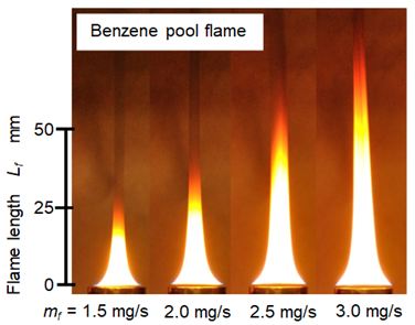
A laminar diffusion flame was stationary formed with this equipment. Figure 4 shows direct photographs of Benzene flame formed by this pool combustion equipment. Flame length Lf was defined as a distance from the pool rim to the flame tip. Lf increased with an increase of mf. Details of flame length change are indicated later in Figure 10. Incandescence of soot combustion and visible smoke at downstream of the flame tip were observed. Soot was formed inside the pool flame and yellow flame sheet was caused by the oxidation of the soot. Mass of the soot exhausted from the pool flame was around 30% of the fuel consumed by the pool combustion. The detail structure of the pool flame was already reported in our previous literatures [11-14]. According these literatures, soot precursor (PAH: Poly-Aromatic Hydrocarbon)) formation started near the liquid fuel surface. Soot formation and oxidation followed the formation of soot precursor. Yellow visible sheet of the flame was the typical evidence of soot oxidation. It means that more soot was formed in the pool flame. Since the luminous yellow flame sheet was observed near the pool rim, there was a possibility that soot formed at the anchor portion of the flame permeated to the fuel pool.
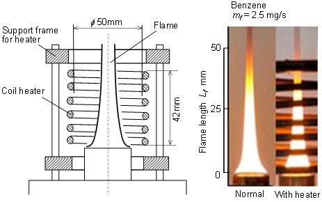
Pool flame and surrounding air entrained into the flame were heated by a coil heater. The scheme of pool flame heating was shown in Figure 5. Height of coil heater was 42 mm, and its inner diameter was 50 mm. Heater surface temperature was set at around 500 oC. The heater could radiatively heat up the flame and convectively heated up the air entrained into the flame, but it did not prevent the air entrainment. Photographs of normal pool flame and heated pool flame at mf = 2.5 mg/s of Benzene were shown in the right side of the figure. Normal Benzene flame was typical pool flame having open flame tip and PM was exhausted from the tip. When this flame was heated, flame length decreased slightly but no obvious change of flame appearance was observed. Since the fuel consumption rates of both flames were adjusted to be the same, fuel surface level of heated flame was lower than that of the normal flame.
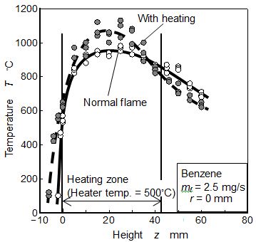
Temperature distributions of normal and heated Benzene flames of mf = 2.5 mg/s were measured by R type thermocouple(dia.: 50 μm). The results along the center axis were indicated in Figure 6. When the Benzene pool flame was heated by the coil heater, temperature at upstream part of the flame increased, and flame length decreased slightly. It means that the more active combustion by heating occurred. Moreover, since the radiative heat flux from the flame was promoted by heating, fuel surface level shifted to lower position than the normal flame. Fuel consumption rate was controlled by the fuel evaporation heat that was supplied from flame zone. Generally fuel surface of low position could not receive much heat from the flame. It means that fuel surface position was the artificially controlled position (see level adjustor in Figure 3) where fuel evaporation heat and supplied heat from the flame was balanced. Active combustion by heating could supply more radiative feedback heat but lower position of fuel surface level prevented the increase of convective feedback heat flux [30]. Since fuel consumption rates of both flame were same, radiative heat flux increased but convective heat flux decreased when the flame was heated. Higher peak temperature and lower temperature gradient near fuel surface were the evidence of heat flux change.
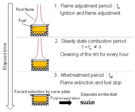
Experiment procedure and precipitate PM collection method are explained in Figure 7. Main steps from flame formation to flame extinction were as follows. First step was a flame adjustment period (ta). It was a transition period from ignition to steady combustion (ta was around 20 sec). The second was a steady state combustion period (t). When the combustion operation continued over 2 hours, stable flame could not be maintained by deposition of solids on the pool rim. So, flame is forcibly extinguished by a cover plate after every one hour operation and the pool rim was cleaned up. And combustion experiment was re-started. Total steady combustion period t was defined by ts × n, where ts was one steady state combustion period (usually one hour) and n was repetition number.
The final step was an aftertreatment period (tat). Flame was forcibly extinguished by the cover plate, and fuel supply was stopped. Then the fuel that was precipitated by permeated PM was remained in the pool. After then, fuel in the pool was evaporated and dried up by room temperature condition. During this period, residue substances in liquid fuel phase deposited on the sampling dish. After sufficient dry-up period (over 20 hours), mass of the deposit on the dish in the fuel pool was measured by the electronic micro-balance. There were two kinds of residue substances. One is the submerged and settled directly on the dish and the other was precipitate PM suspended in the liquid fuel. The residue collected by this treatment was the total mass of above two kinds of substances. Here the total of these substances was regarded as the deposit that was permeated from the flame into liquid pool and finally settled on the bottom.
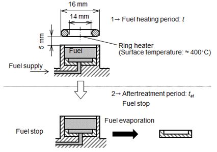
In this study, residue substance produced by fuel heating with a ring heater (without pool flame condition) was also attempted. Figure 8 shows scheme of fuel heating by a ring heater and residue measurement method of this case. The ring heater (inner diameter = 14 mm, outer dimeter = 16 mm) was mounted at position of z = 5 mm. Surface temperature of it was set at around 400 oC. To promote fuel pyrolysis in liquid phase and liquid surface exposed by hot air, this temperature was set as a slightly lower temperature than auto ignition temperature. After sufficient fuel heating (heating time was th), fuel supply was stopped and fuel in the pool was dried up by room temperature. Deposit formed by direct fuel pyrolysis was evaluated by the same manner as explained previously.
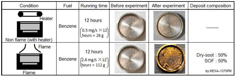
Deposit on the fuel pool bottom after fuel heating by the ring heater (without flame) and pool diffusion combustion were investigated. Appearances of the dishes after heating and steady combustion periods of 12 hours were shown in Table 1.
As for the case of fuel heating by the ring heater, fuel pool after heating of 12 hours was not contaminated and luster of the dish was only lost after drying. It was considered that deposit did not appear after heating by 400 oC heater for a long time. Boiling point of Benzene was 80.1 oC and no fuel pyrolysis was induced even though Benzene vapor temperature was 600 oC [39]. Then it was reasonable that no deposit was accumulated in the fuel pool during 12 hours radiative and convective heating.
Under the condition of flame formation on the fuel pool, the color of fuel pool changed to dark after pool combustion for 12 hours, and a deposit appeared on the dish settled at the fuel pool bottom. Then, composition of the deposit on the dish was analyzed by a combustion type PM analyzer (HORIBA, MEXA-1370PM), and found out that it contained around 50 % of SOF (Soluble Organic Fraction) and around 50 % of dry-soot (elemental carbon). Since there was no possibility of dry-soot and PAH (Poly-Aromatic Hydrocarbon) formation in liquid fuel phase, it was considered that the deposit was PM or soot formed in pool flame and permeated into the fuel pool.
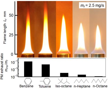
Exhaust PM measurement from pool flame of various fuels were performed as one of our previous study [40]. As shown in Figure 9, PM exhaust rates of Benzene and Toluene were higher than those of iso-Octane, n-Heptane and n-Octane. Yellow diffusion flame sheet near pool rim and open flame tip were typical feature of Benzene and Toluene flames. Yellow diffusion flame near pool rim meant that the soot formation started near pool rim. Open flame tip meant that formed soot was not completely oxidized in the flame and emitted out from open flame tip as exhaust PM. On the contrary, paraffin type fuel had blue flame sheet near the pool rim and closed flame tip. It meant that soot formation zone located apart from the pool rim and formed soot was almost completely oxidized in the flame. It resulted low exhaust PM formation rate shown in the under part of the Figure.
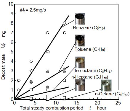
Relationship between total steady combustion period and mass of the deposit on the fuel pool bottom was investigated. Deposits obtained for various fuels such as paraffin group (n-Heptane and n-Octane), iso-Alkane (iso-Octane), and aromatic group (Benzene and Toluene) are shown in Figure 10. The color of solid deposit substance was dark brown and looked like PM deposit.
As for the paraffin fuels such as n-Heptane and n-Octane, fuel pool was not contaminated after pool combustion of long time operation, and deposit mass could not be detected. As for iso-Octane and aromatic fuels, fuel pool was contaminated by pool combustion flame. Deposit mass increased with an increase of steady combustion period.
Fuel depending tendency of deposit mass was similar to that of PM exhaust mass from the tip of pool flame shown in Figure 9. It suggests that soot formation near fuel pool surface resulted large amount of the deposit.
However, deposit formation rate was considerably lower than the PM exhaust rate. For example, deposit formation rate from Benzene flame was around 0.00018 mg/s but PM exhaust rate for the same flame (mf =2.5 mg/s) was around 0.25 mg/s. As a standpoint of internal engine combustion, precipitate PM in the fuel film and deposit on the piston surface was not cleaned up by every exhaust process of the cycle. They were dried up in the cylinder and accumulated on the surface during long time engine operation. Then the deposit problem should not be neglected even though the formation rate of it was extremely lower than the exhaust PM.
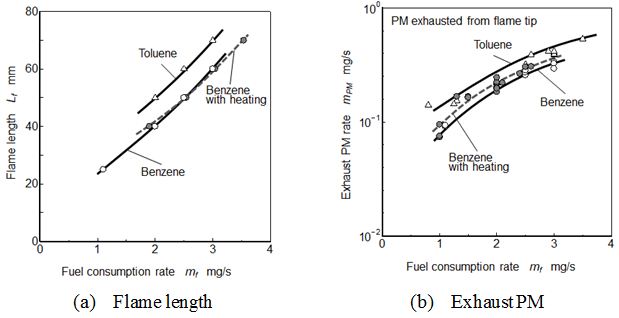
Figure 11 indicated flame lengths and exhaust PMs for different pool flames. Toluene flame was longest flame length and exhaust PM. Flame length increased with an increase of fuel consumption rate (Figure 11(a)). There were no obvious differences in Benzene flames with and without heating. Exhaust PM showed the positive relationship with flame length and also there were no obvious differences in the Benzene flames (Figure 11(b)).
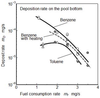
Figure 12 shows relationships between fuel consumption rate and deposit formation rate on the pool bottom for Benzene and Toluene. Result of Benzene flame with heating condition was also shown in this figure. Deposit formation rate showed inverse relationship with flame length and exhaust PM, and a small pool flame formed more deposit than the large flame.
As for the normal Benzene flame, deposit formation rate at mf = 1.0 mg/s was around 3x10⁻⁴ mg/s. Deposit formation rate at Toluene flame was lower than that of Benzene flame. Both rates of Benzene and Toluene flames decreased with an increase of mf. Exhaust PM rate from the tip of Benzene flame increased with an increase of mf. Decreasing tendency of deposit formation rate relating fuel consumption rate was not agreed with that of exhaust PM shown in Figure 11(b). Further in the case of Benzene flame under heating condition, deposit formation rate was lower than that of normal Benzene flame.
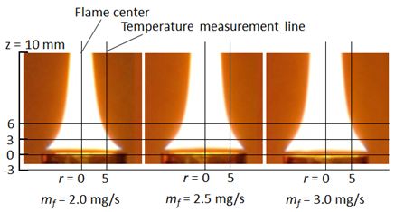
Center line temperature of pool flame was one of the representative temperatures that indicated the general feature of the flame. However it did not indicate the average temperature of the flame because of temperature distribution existed in the flame. To discuss the in-flame temperature effect on PM permeation phenomena from pool diffusion flame to liquid pool, radial average temperature or effective location temperature for PM permeation was needed. Instead of the center line temperature, axial temperature distribution along the r = 5 mm line was used in this study.Figure 13 shows the relative position between flame sheet and temperature measurement line set at r = 5 mm radial position. This radial position was chosen as a representative affecting temperature considering area mean radius (r = 5.3 mm) and flame sheet location.
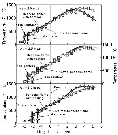
Figure 14 shows temperature distributions along z axis at r = 5 mm near fuel surface of Benzene flames at mf = 2.0, 2.5 and 3.0 mg/s. As for the upstream part of the flame (lower than z = 0 mm, below the rim position) shown in the Figure, temperature at Benzene flame with heating condition was higher than that of the normal flame of Benzene. It was caused by the regression of liquid fuel surface.
As for mf = 2.0 mg/s shown in the upper part of the figure, peak temperature appeared around z = 4.5 mm at normal Benzene flame, and its region was flame zone. Maximum temperature position of heated flame was lower than that of normal flame. The temperatures of both flames near fuel surface were almost same. However, fuel surface position at heated flame was lower than that of the normal flame, and temperature gradient (dT/dz) at just above the fuel surface under flame heating was lower than that of the normal flame. Nano size PM did not formed near the anchor portion of diffusion flame, and upstream direction flux of soot particle need some driving force such as Brownian motion force and thermophoresis [13,14,41]. Generally, nano scale particles were affected by thermophoresis in higher temperature gradient field. It might be considered that soot particles formed in fuel vapor region were forced to penetrate to fuel surface and to permeate into the fuel pool by thermophoresis. Lower deposit formation rate under heating condition might be caused by a decrease of weak thermophoresis effect corresponding to low temperature gradient.
As for mf = 2.5 mg/s shown in the middle part of the figure, fuel surface position was around z = -2.2 mm under normal flame condition, and was higher than that of heated flame (fuel surface position under heater flame was around z = -2.6 mm). These positions were higher than those of mf = 2.0 mg/s. Further, the fuel surface positions under both conditions of the normal and heater flames at mf = 3.0 mg/s shown in the lower part seemed to be much higher than those of mf = 2.5 mg/s. However, flame length was elongated with mf increasing, and maximum temperature position shifted to downstream.
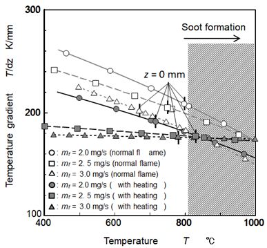
Relationship between temperature and temperature gradient (dT/dz) obtained by differentiating temperature distribution along z axis at r = 5 mm near fuel pool was shown in Figure 15. Here, by the investigation of soot formation under low temperature condition (600 oC – 1200 oC) using a flow reactor and by the visualization of soot formation region inside the flame using a LII technique in our previous study, it was reported that soot formation occurred under temperature condition of over around 800 oC (depending on conditions such as O2 concentration). This temperature condition is shown by hatching area in the Figure [14,39].
For all conditions shown in the figure, temperature gradients near fuel pool decreased with an increase of temperature. At temperature range of less than around 800 oC, temperature gradient under heated flames were lower than those of normal flames, and decreased with mf increase. As mentioned above, it was thought that nano scale particles were affected by thermophoresis in higher temperature gradient field, and thermophoresis effect increased with an increase of temperature gradient. Deposit formation rate shown in Figure 12 had clear relationship with temperature gradient at around 500 oC. In other words, heating flame showed low temperature gradients and low deposit formation rates. Then, it was estimated that soot particle formed near fuel surface penetrated into the liquid pool and deposited on the pool bottom. Driving force of this penetration might be the thermophoresis diffusion of soot particle near the fuel surface but we need more study to confirm the thermophoresis diffusion and behavior of soot particle that moved and captured by liquid surface.
The thermophoresis velocity of nano-size particle was obtained using NaCl particles [42-44]. By using these reports, it was roughly estimated that 2.2 cm/s for 100 nm particle and 1.2 cm/s for 200 nm particle when the temperature gradient of 200 K/mm was given under atmospheric and 600 oC condition. On the other hand, average upward vapor velocity at fuel surface was around 1.1 cm/s at 2.5 mg/s condition. Then it was very likelihood that soot particle permeated from pool flame to liquid pool surface because of higher temperature gradient than 200 K/mm. When the fuel consumption rate decreased, peak temperature position and soot formation zone in the flame became approaching to the fuel surface and temperature gradient near the fuel surface increased. Also soot concentration gradient near the surface increased as decreasing the flame size (overall flame height) if the soot formation rate per unit space was constant. These tendencies suggested that small pool flame taken place in an engine cylinder became more risky flame where soot particle was permeated and formed precipitate PM in the fuel film. It remained as the deposit after dry-up of fuel film.
Carbonaceous substance deposited on the bottom of fuel pool during a pool diffusion combustion with liquid fuel was measured as the deposit. Temperature gradient near fuel surface was carefully measured inside the small laminar diffusion flame formed on the 16 mm dia. fuel pool. Deposit under flame heating condition was also measured and compared with the normal flame deposit. The main results are summarized as follows.
(1) Deposit formation rate of aromatic group was the highest among paraffin, iso-alkane and aromatic groups. Furthermore, deposit formation rate of Benzene (C6H6) flame was higher than that of Toluene (C7H8).
(2) Deposit formation rate at lower fuel consumption rate was high, and deposit formation rate decreased with increasing of fuel consumption rate.
(3) Deposit from Benzene pool flame in heating condition was lower than that from the normal pool flame.
(4) Temperature gradient near fuel surface was considered as the main driving force of soot permeation from soot formation zone to liquid fuel pool. Low deposit formation rates in large pool flame and heating pool flame were caused low temperature gradient neat fuel surface.
(5) Above deposit formation behavior could be explained by the thermophoresis behavior of PM existed high temperature gradient field near fuel surface.